Why Threaded Inserts Matter in Plastic Part Design
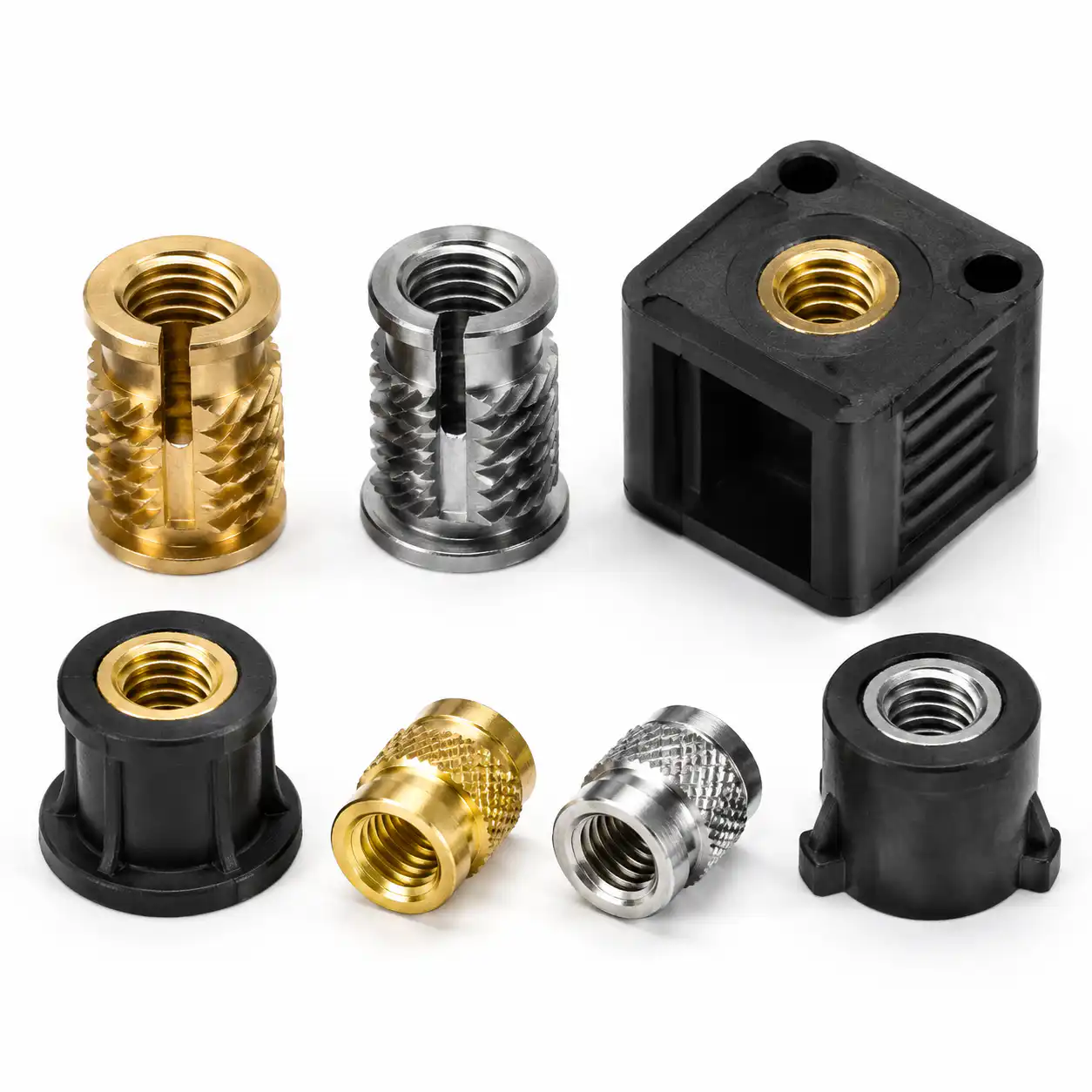
Plastic injection-molded parts present a fundamental fastening challenge: thermoplastics lack the compressive strength, creep resistance, and thread durability required for reliable bolted joints, particularly in applications requiring repeated assembly and disassembly. Directly threading a screw into a plastic boss may work for a single assembly cycle in low-stress applications, but it is fundamentally unreliable for joints that must maintain preload, withstand vibration, or survive multiple service cycles. Threaded inserts solve this problem by providing a durable metal thread form within the plastic component, distributing fastener loads across a larger area and maintaining joint integrity throughout the product lifecycle.
The insert transforms the failure mode of a bolted joint in plastic. Without an insert, the limiting factor is typically the shear strength of the plastic thread, which can be as low as 10 to 30 MPa. With a properly specified insert, the limiting factor becomes the tensile strength of the bolt itself, increasing joint capacity by a factor of 3 to 10 and enabling predictable, repeatable assembly torque values.
Apply the numerical examples to a defined joint. The ranges in this guide are starting references, not acceptance limits for a specific insert, resin or assembly. Confirm the insert supplier’s drawing and hole recommendations, then qualify the actual molded part and installation. The assembled joint can fail by pull-out, rotation, boss damage or preload loss before the bolt reaches its strength limit. SPIROL’s performance guidance explains why insert performance requires application-specific evaluation.
For a complete part project, the threaded insert design and installation guide connects the insert specification with molding, installation and assembly requirements.
Threaded Insert Types: Technologies and Selection Criteria
Heat Staking Inserts
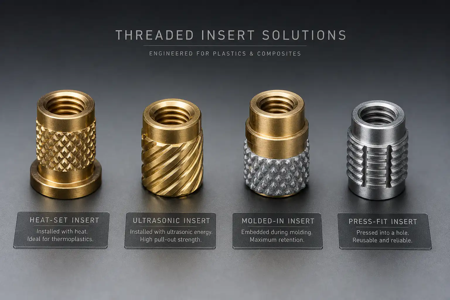
Heat staking inserts — also known as thermal inserts — are installed by heating the insert to a temperature above the plastic’s softening point and pressing it into a molded or drilled hole. The heated insert melts and displaces the surrounding plastic, which flows into knurls, undercuts, and retention features on the insert’s outer surface. Upon cooling, the plastic solidifies around the insert, creating a mechanical interlock that resists both pull-out and rotational forces.
Heat staking is the most accessible and widely used insertion method for low to medium production volumes. Installation equipment ranges from a simple soldering iron with a custom tip for prototype and low-volume work to automated hot-air or induction heating systems capable of installing thousands of inserts per hour. The process is tolerant of minor hole size variations and provides excellent retention strength when the insert features are properly matched to the plastic material.
Limitations include the risk of localized thermal degradation if the installation temperature is too high or dwell time is excessive, cosmetic issues from displaced plastic at the insertion site for visible surfaces, and a practical speed limitation compared with molded-in inserts for very high volumes. Typical cycle time for manual installation is 3 to 8 seconds per insert; automated systems can achieve 1 to 2 seconds.
Ultrasonic Inserts
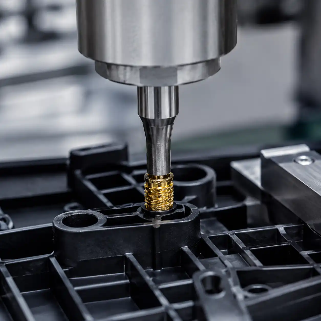
Ultrasonic insertion uses high-frequency vibration — typically 20 to 40 kHz — transmitted through a horn to generate localized frictional heating at the insert-plastic interface. The plastic melts in a thin layer immediately surrounding the insert, flowing into retention features, and solidifies rapidly when vibration ceases. Ultrasonic insertion offers several advantages over heat staking: faster cycle time of 0.5 to 2 seconds per insert, lower overall heat input reducing thermal degradation risk, cleaner appearance with minimal displaced plastic on the surface, and superior process control with precisely programmable energy, amplitude, and trigger force parameters.
Ultrasonic insertion is the preferred method for medium to high production volumes where insert location is accessible to the ultrasonic horn. The primary limitation is geometric: the horn must have a clear, perpendicular approach to the insert location, and adjacent features or walls may interfere with horn access. Inserts designed specifically for ultrasonic installation feature optimized geometries — typically a tapered lead-in and energy-directing rings — that concentrate ultrasonic energy at the interface for rapid, consistent melting.
Molded-In Inserts
Molded-in inserts are placed into the mold cavity before each injection cycle, and the molten plastic flows around the insert, encapsulating it within the molded part. This approach provides the highest possible retention strength because the plastic fully encapsulates all retention features without the thermal history of post-mold insertion. Molded-in inserts eliminate all secondary installation operations, making them cost-effective for very high production volumes despite the increased mold complexity and cycle time.
The disadvantages are significant and must be carefully evaluated. Manual insert loading adds 5 to 15 seconds to the molding cycle per insert, reducing production throughput. If an insert is misloaded, displaced during mold closing, or omitted entirely, the mold can be damaged — a $5 insert loading error can destroy a $50,000 mold cavity. Automated insert loading systems reduce these risks but add capital cost of $20,000 to $100,000 per mold. Mold design must incorporate precise insert locating features with adequate clearance for thermal expansion, and the mold steel around the insert must be hardened to resist damage from repeated insert contact. For high-temperature resins such as PPS and PEEK, mold temperatures of 140°C to 200°C demand insert materials and locating features that maintain dimensional accuracy at elevated temperature.
Press-In Inserts
Press-in inserts rely on an interference fit between the insert’s knurled or barbed outer surface and a precisely sized hole in the plastic part. Installation is by simple axial pressing — no heat or ultrasonics required. Press-in inserts are the fastest installation method at 0.3 to 0.8 seconds per insert and require the simplest equipment. However, they provide the lowest retention strength of all insert types because the purely mechanical interference fit does not benefit from the plastic flow and encapsulation that heat staking or ultrasonic insertion provides.
Press-in inserts are best suited for applications with low pull-out and torque requirements, where the joint is primarily in shear rather than tension, and where installation speed and simplicity are paramount. Hole diameter tolerance is critical — typically plus 0.05 mm to plus 0.10 mm — and must be maintained consistently across the production run. Tapered-hole press-in designs improve installation consistency by providing a gradual interference increase rather than an abrupt engagement.
Self-Tapping Screws (Thread-Forming for Plastics)
Self-tapping screws for plastics — distinct from sheet metal screws — are designed with specialized thread profiles that form, rather than cut, threads in the plastic boss during the first assembly. The PT screw (Plastite, or trilobular thread-forming profile) is the industry standard, with a trilobular cross-section that reduces driving torque while providing high thread engagement. Self-tapping screws eliminate insert cost and installation labor entirely, making them the most economical fastening solution for single-assembly or very-low-disassembly applications.
The limitations are critical: thread-forming screws are generally limited to 1 to 5 assembly cycles before thread degradation significantly reduces joint strength; strip-out torque is lower and less predictable than insert-based joints; and boss design — particularly the pilot hole diameter — must be precisely controlled to achieve consistent performance. The pilot hole is typically 70% to 80% of the screw major diameter, with specific recommendations provided by the screw manufacturer based on the specific plastic material and glass fiber content.
Insert Material Selection
| Материал | Сила | Устойчивость к коррозии | Electrical Conductivity | Типовые применения | Относительная стоимость |
|---|---|---|---|---|---|
| Brass (C36000) | Умеренный | Хорошо | Проводящий | General-purpose, electronics enclosures, consumer products | Низкий |
| Steel (12L14) | Высокий | Poor (requires plating) | Проводящий | High-strength structural joints, automotive under-hood | Низкий |
| Stainless Steel (303/304) | Высокий | Превосходно | Проводящий | Medical devices, food equipment, marine, chemical processing | Средний |
| Stainless Steel (316) | Высокий | Superior | Проводящий | Implantable medical, severe chemical exposure, offshore | Высокий |
| Aluminum (6061-T6) | Низкий–умеренный | Good (with anodizing) | Проводящий | Lightweight electronics, aerospace, thermal management | Средний |
Brass inserts dominate general-purpose applications due to their excellent machinability enabling precise, low-cost production; natural corrosion resistance sufficient for indoor and protected outdoor environments; thermal conductivity that benefits heat staking installation by conducting heat rapidly from the installation tip into the surrounding plastic; and compatibility with a wide range of plastic materials without galvanic corrosion concerns. For structural applications requiring high pull-out or torque resistance — particularly in glass-fiber-reinforced materials — steel inserts provide 50% to 100% higher strength at a material cost comparable to brass, though zinc or nickel plating is required for corrosion protection. Stainless steel inserts are specified when corrosion resistance is non-negotiable, as in medical, marine, and food processing applications, at a cost premium of 2x to 4x compared with brass.
Boss Design Guidelines for Threaded Inserts
| Параметр проектирования | Heat/Ultrasonic Inserts | Molded-In Inserts | Press-In Inserts |
|---|---|---|---|
| Boss OD to Insert OD Ratio | 2.0 – 2.5x | 2.5 – 3.0x | 2.5 – 3.5x |
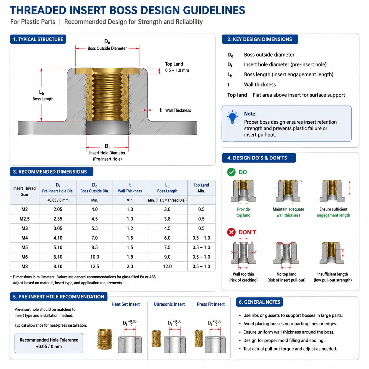
| Hole Diameter (vs Insert OD) | Insert OD minus 0.2 to 0.3 mm | Insert OD plus 0.05 to 0.10 mm | Insert OD minus 0.3 to 0.5 mm |
| Hole Depth (vs Insert Length) | Insert length plus 1.5 – 2.0 mm | Insert length plus 0.5 mm | Insert length plus 0.5 mm |
| Boss Height | Insert length plus 0.5 mm | Insert length plus 1.0 mm | Insert length plus 0.5 mm |
| Угол наклона | 0.5° – 1.0° | 0° – 0.5° | 0.5° – 1.0° |
Boss design is the single most critical factor in insert joint performance. The boss outside diameter must provide sufficient hoop strength to resist the radial expansion forces generated during insert installation and bolt tightening. Insufficient boss wall thickness is the most common cause of boss cracking — either immediately during installation or after environmental conditioning when residual stresses relax or concentrate. Bosses should be connected to the main part wall with gussets or ribs to distribute installation and service loads into the larger structure rather than concentrating them at a thin boss-to-wall junction. The gusset thickness should be 50% to 60% of the boss wall thickness to avoid creating sink marks on the opposite surface.
Ознакомьтесь с rib and boss design guide for the boss-to-wall connection, support and local geometry.
Используйте injection molding wall thickness guide when checking the boss, ribs and adjoining part wall together.
Pull-Out Strength and Torque Resistance
Pull-out strength — the axial force required to extract the insert from the plastic — is a function of insert design, plastic material properties, boss geometry, and installation quality. For a properly specified and installed brass heat staking insert in unreinforced nylon (PA6), typical pull-out values range from 500 N for an M3 insert to 3,500 N for an M8 insert. Glass fiber reinforcement increases pull-out values by 20% to 40% due to the higher shear strength of the reinforced material, though very high glass content above 40% can reduce pull-out strength by making the material more brittle and less able to flow into insert retention features during installation.
Torque resistance — the rotational torque required to spin the insert in the plastic — is primarily determined by the anti-rotation features on the insert’s outer surface. Knurled or diamond-pattern surfaces provide superior torque resistance compared with straight knurls or smooth surfaces. For an M5 brass insert in PA66, typical installation torque for a mating bolt ranges from 3 to 5 Nm, while the insert’s rotational failure torque should exceed 6 to 8 Nm to provide adequate safety margin.
Common Insert Failures and Solutions
- Boss Cracking During Installation
- Caused by insufficient boss wall thickness, excessive interference between insert and hole, or installation temperature too low (plastic does not soften adequately). Solution: increase boss OD to minimum 2.0x insert OD, verify hole diameter within specification, and confirm installation temperature appropriate for the specific plastic material.
- Insert Pulls Out Under Load
- Caused by insufficient insert length for the applied load, inadequate boss wall thickness, or improper installation (insert not fully seated or plastic did not adequately flow into retention features). Solution: increase insert length to provide greater engagement area, verify boss dimensions, and validate installation process parameters including temperature, force, and dwell time.
- Insert Rotates During Bolt Tightening
- Caused by inadequate anti-rotation features on the insert, installation temperature too high causing excessive plastic degradation, or incorrect insert specification for the application torque. Solution: select insert with aggressive knurling or hexagonal outer shape, verify installation parameters, and consider ultrasonically installed inserts which provide superior anti-rotation performance.
- Plastic Flash in Threads
- Caused by plastic flowing into the internal threads during heat staking or ultrasonic installation, typically due to excessive installation force or temperature. Solution: use inserts with closed-end design or internal thread protection, reduce installation force, and employ inserts specifically designed with flash-blocking features at the thread entry.
- Galvanic Corrosion at Insert-Plastic Interface
- Caused by electrochemical incompatibility between the insert material and additives in the plastic, particularly in humid or wet environments. Solution: select corrosion-resistant insert materials (brass or stainless steel) appropriate for the service environment, or apply barrier coatings to steel inserts to isolate them from the plastic and environment.
Process Selection Decision Matrix
| Фактор | Heat Staking | Ультразвуковой | Molded-In | Press-In |
|---|---|---|---|---|
| Annual Volume Suitability | 1,000 – 100,000 | 10,000 – 1,000,000+ | 100,000+ | 1,000 – 50,000 |
| Cycle Time per Insert | 3 – 8 seconds | 0.5 – 2 seconds | Added to mold cycle | 0.3 – 0.8 seconds |
| Retention Strength | Высокий | Очень высокий | Максимальный | Низкий–средний |
| Стоимость оборудования | $500 – $15,000 | $5,000 – $50,000 | $20,000 – $100,000 (automation) | $1,000 – $10,000 |
| Risk to Mold | None (post-mold) | None (post-mold) | Significant (mold damage risk) | None (post-mold) |
| Insert Cost | Стандарт | Slightly Higher (optimized geometry) | Стандарт | Стандарт |
Часто задаваемые вопросы
Какое решение с резьбовыми вставками является наиболее экономически выгодным для средних объемов производства?
При годовых объемах производства от 10 000 до 100 000 единиц ультразвуковая вставка, как правило, обеспечивает оптимальный баланс между скоростью монтажа, качеством соединения и инвестициями в оборудование. Более высокая стоимость оборудования по сравнению с термической закрепкой компенсируется в 3–4 раза более быстрым временем цикла и превосходной стабильностью процесса. Кроме того, ультразвуковая вставка вызывает меньшую термическую деградацию и реже приводит к дефектам внешнего вида, чем термическая заклепка. При годовых объемах производства менее 10 000 единиц термическая заклепка, как правило, является более экономически выгодным решением благодаря минимальным инвестициям в оборудование. При объемах, превышающих 500 000 единиц, впрессованные вставки с автоматической загрузкой становятся экономически привлекательными, несмотря на более высокие первоначальные инвестиции.
Можно ли использовать резьбовые вставки в стеклопластике?
Yes, and they are strongly recommended — the abrasive nature of glass fibers quickly degrades directly tapped threads in reinforced plastics. However, glass-filled materials require specific considerations: heat staking temperature must be adjusted upward because filled materials have higher softening temperatures and lower melt flow, reducing the material’s ability to flow into insert retention features. Ultrasonic insertion is generally preferred for GF-reinforced materials because the localized frictional heating is more effective at producing flow in filled materials. Boss wall thickness should be increased by 10% to 20% compared with unfilled material to compensate for the reduced ductility. Standard inserts generally perform well up to 30% glass fiber content; above this level, specialized insert geometries with deeper, more aggressive knurling patterns improve retention in the stiffer, more brittle material.
Как определить размер резьбы и длину вставки для конкретного применения?
Размер резьбы вставки должен соответствовать указанному крепежному элементу; наиболее распространенные размеры для применения в пластиковых изделиях — от M2,5 до M8 (метрическая резьба) и от #4-40 до 5/16-18 (UNC). Длина вставки определяется требуемой прочностью на вырыв и доступной глубиной выступления. Как правило, длина вставки должна составлять не менее 1,5 диаметра резьбы для применений с низкой нагрузкой и от 2,5 до 3 диаметров резьбы для конструкционных применений. Конкретное усилие выдергивания можно рассчитать по формуле: F = π × D × L × τ, где D — наружный диаметр вставки, L — длина зацепления, а τ — предел прочности на сдвиг пластика (обычно от 25 до 55 МПа для инженерных термопластов). Для целей проектирования к этому расчётном значению следует применять коэффициент безопасности от 2,0 до 3,0.
Какие существуют методы контроля качества при установке резьбовых вставок?
Проверка качества установки вставок должна включать: визуальный осмотр на предмет полной установки (вставка должна находиться на одном уровне с поверхностью выступления или немного ниже, без пластиковых заусенцев на резьбе), контроль размеров положения вставки (обычно плюс-минус 0,25 мм для общего применения, более жесткие допуски для критических мест), испытание на крутящий момент на основе статистической выборки для проверки соответствия установленной вставки минимальному сопротивлению крутящему моменту, а также испытание на вытягивание во время валидации процесса с использованием растяжителя для подтверждения того, что процесс установки обеспечивает заданную прочность удержания. Для критически важных применений может быть предписано испытание на крутящий момент по стандарту 100%. Кроме того, рассечение образцов деталей во время валидации процесса позволяет оценить качество течения пластмассы в фиксирующие элементы вставки и выявить любые пустоты или недостаточную герметизацию.
When should I avoid using threaded inserts and choose an alternative fastening method?
Threaded inserts may not be the optimal fastening solution when: (1) the joint requires only a single assembly with no disassembly — snap-fits or self-tapping screws may be more economical; (2) very high production volumes exceed 5 million units annually, where molded-in inserts or alternative fastening strategies should be evaluated against the cumulative insert and installation cost; (3) wall thickness is too thin to accommodate a boss meeting the minimum OD-to-insert-OD ratio, in which case through-bolts with nuts, bonded inserts, or redesigning the part to provide adequate boss geometry are alternatives; (4) the application demands electrical isolation between joined components, where plastic snap-fits, adhesively bonded joints, or insulated insert designs are required; and (5) weight is the absolute paramount design criterion, as metal inserts add mass to plastic components.
Request a Plastic Part and Insert Review
For an injection-molded component with threaded inserts, send the part and assembly drawings. Nylon Plastic can review material selection, boss geometry, molding or post-molding installation and inspection as one finished-part project.
Что необходимо учесть и согласовать до составления коммерческого предложения
- Provide CAD and revision, resin grade and reinforcement, thread size, insert drawing or manufacturer part number, and any permitted alternatives.
- Identify molded-in or post-installed construction, mating fastener and component, access, installation depth, assembly torque, pull-out requirement, service load and environment.
- State first and annual quantity, destination and target timing. Define the sample test method, conditioning, acceptance limits, inspection records and who approves the assembly.
Ask the quotation to distinguish insert sourcing or customer-supplied inserts, tooling, molded parts, installation, assembly and validation. Specify whether you need the complete plastic component or insert hardware alone so the team can confirm the relevant supply scope.