Injection mold cooling system design should remove heat uniformly and repeatably from the cavity, core, inserts and thick sections. The target is not simply the shortest cycle. A fast cycle that leaves hot spots, unequal shrinkage or an unstable ejection condition can create warpage, gloss variation, dimensional drift and repeated trial work. A robust design connects resin heat load, wall thickness, gate location, mold steel, cooling circuits, coolant flow, production volume and inspection requirements.
For a buyer, the useful deliverable is a cooling concept that can be reviewed before steel is cut and verified during mold trials. Ask for the circuit map, inlet and outlet points, expected temperature difference, pressure-drop assumptions, maintenance access and the dimensions or cosmetic zones most sensitive to thermal imbalance. Cooling should be reviewed together with gate, packing, draft, ejection and part geometry because those systems interact in the same molded part.
The engineering function of mold cooling
| Cooling objective | What it controls | Evidence during validation | Risk when overlooked |
|---|---|---|---|
| Uniform heat removal | Core/cavity temperature balance and local shrinkage | Surface-temperature map, coolant in/out data and cavity comparison | Warpage, twist, gloss variation and dimensional movement |
| Controlled cycle | Time from fill to safe ejection | Cycle study, ejection condition and free-state dimensions | Sticking, distortion, long cycle or false cycle-time savings |
| Hot-spot management | Heat around bosses, ribs, inserts and thick walls | Thermal imaging, mold-temperature readings and sectioned samples | Sink, voids, local shrinkage and surface defects |
| Cavity-to-cavity balance | Repeatability across multi-cavity tools | Per-cavity temperature, weight and dimensional data | One cavity passes while another drifts or rejects |
| Maintainability | Flow, pressure and performance over tool life | Flow check, filter/scale record and accessible circuit connections | Gradual process drift that is mistaken for material or machine variation |
Use the mold design and mold making service page for the wider tooling process. The melt versus mold temperature guide explains why controller setpoints do not prove the cavity-surface condition. The warpage guide is useful when the cooling concept is being evaluated against a measured distortion pattern.
Inputs that control the design
Start with the resin and the part rather than selecting a channel pattern from a template. Resin heat capacity, melt-temperature range, crystallization behavior, filler content and shrinkage influence the amount and timing of heat that must be removed. Semi-crystalline resins such as PA, POM, PP and PEEK may need a controlled mold temperature to achieve the required crystallinity and dimensions. Glass-filled grades add directional shrinkage and can make a small thermal imbalance more visible as warpage.
Map the part wall thickness, ribs, bosses, inserts, sealing surfaces, cosmetic faces, mounting planes and critical datums. Thick sections and metal inserts can hold heat longer than surrounding walls. A gate near a cosmetic face or a long thin flow path may create a different thermal history from a centrally gated part. The cycle target, cavity count, machine connections, coolant type, available pressure and maintenance access should be fixed before the circuit layout is approved.
- Resin grade, filler, melt range, shrinkage and annual volume.
- Wall-thickness map, ribs, bosses, inserts, texture and critical surfaces.
- Gate location, flow direction, packing requirement and expected hot spots.
- Tool steel, insert materials, mold size, cavity count and automation needs.
- Coolant type, supply temperature, flow target, pressure drop and connection layout.
- Inspection datums, flatness, profile, gloss, sealing and assembly requirements.
Channel placement and circuit balance
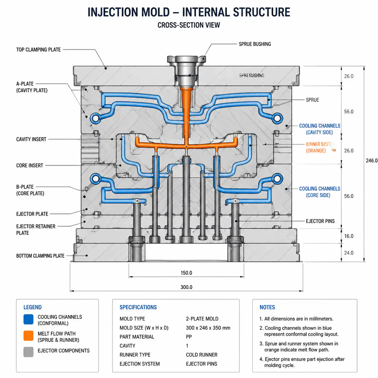
Cooling channels should follow the heat pattern of the part while leaving enough steel for strength, shutoffs, inserts and machining. Distance from the cavity surface, channel spacing, channel diameter, circuit length and the number of parallel circuits influence heat transfer and pressure drop. The exact dimensions depend on the tool size, steel, resin, part geometry and manufacturing method; universal spacing rules should be treated as a starting point for analysis, not a final approval.
Series circuits are simple and compact, but the coolant temperature can rise along the path. Parallel circuits can reduce temperature rise but need balanced resistance and accessible flow checks. Long circuits, sharp turns, small passages and poorly matched branches can cause one area to run hotter even when the controller supply temperature looks normal. Record circuit identity and flow direction so a maintenance team can identify a blocked or restricted branch.
Baffles and bubblers can bring cooling into narrow cores, slides and deep features. They need enough clearance, correct orientation and a serviceable connection. Inserts may need independent circuits or a conductive material strategy. Conformal cooling can place passages closer to complex geometry and hot spots, but it adds manufacturing, sealing, inspection and repair considerations. The correct option is the one that meets thermal balance and tool-life requirements with a maintainable design.
Material and production-volume effects
| Part or material condition | Cooling concern | Design response | Validation focus |
|---|---|---|---|
| Semi-crystalline resin | Crystallization and shrinkage depend on thermal history | Control mold temperature and cooling balance rather than only shortening cycle | Conditioned dimensions, crystallinity-related movement and flatness |
| Glass-filled resin | Fiber orientation adds directional shrinkage | Balance flow and cooling around gates, ribs and long walls | Flow/transverse dimensions, warpage and cavity comparison |
| Thick bosses or ribs | Local heat remains after surrounding walls are ejected | Add focused cooling, core relief or geometry correction where feasible | Sink, voids, local profile and post-ejection movement |
| High-volume production | Scale, blockage and thermal drift accumulate over time | Provide flow checks, filters, accessible connections and maintenance limits | Flow/temperature trend and preventive-maintenance records |
| Cosmetic textured face | Surface replication and gloss respond to local thermal condition | Keep surface temperature balanced and protect texture zones from hot spots | Visual boundary sample, gloss/texture check and surface map |
Tooling options and cost trade-offs
Drilled cooling circuits are familiar, economical and easy to service when the geometry allows a direct path. Baffles and bubblers extend cooling into narrow areas but add components, seals and potential blockage points. Independent insert cooling can improve a local hot spot, but it may add connections and reduce available steel. Conformal cooling can be valuable for complex or high-volume parts where a conventional circuit cannot follow the heat pattern, yet the toolmaker must control channel accuracy, pressure integrity, surface finish and repair strategy.
| Option | Выгода | Risk or cost consideration | Оптимальный вариант |
|---|---|---|---|
| Drilled series circuit | Simple construction and familiar maintenance | Temperature rise along long paths and limited geometry access | Moderate geometry with direct cooling paths |
| Parallel circuits | Can reduce temperature rise and separate zones | Needs balanced resistance and flow verification | Multi-zone or multi-cavity tools |
| Baffle or bubbler | Reaches narrow cores and deep features | Small passages, wear, blockage and service access | Core pins, slides and restricted inserts |
| Independent insert circuit | Targets a known hot spot | Extra seals, fittings and assembly complexity | Large inserts, bosses or local heat loads |
| Конформное охлаждение | Follows complex geometry and can improve balance | Higher tooling cost, inspection and repair requirements | Complex, high-volume or cycle-sensitive parts |
Failure modes and corrective actions
Warpage may follow a hot core, a blocked circuit, unequal cavity cooling, packing imbalance or fiber orientation. A long cycle may indicate insufficient heat-transfer area, a cautious ejection limit or a hot spot that has not been addressed. Scale and corrosion can reduce flow over time. Leakage may come from a damaged plug, thin wall, seal or connection. When a defect appears, compare the cavity map, coolant flow, surface temperatures, cycle and free-state dimensions before changing global process settings.
A process adjustment can sometimes reduce a symptom, but it cannot make an inaccessible or unbalanced circuit maintainable. If the mold temperature is changed to compensate for one hot spot, another cavity or cosmetic surface may move outside the requirement. The corrective action should state whether it is a process change, cooling maintenance action, circuit modification, insert change or part-design correction.
Validation at DFM, mold trial and production approval
- DFM review: map walls, ribs, bosses, inserts, gates, cosmetic zones and critical datums against the proposed circuit layout.
- Flow and thermal review: confirm coolant path, connection, expected flow direction, pressure drop and hot-spot strategy.
- Mold trial: record supply/return temperatures, flow if available, cavity-specific conditions, cycle, ejection and sample identity.
- Thermal observation: use surface measurements or thermal imaging after the mold reaches a stable condition, not immediately after startup.
- Dimensional approval: inspect free-state flatness, profile, hole position, sealing and assembly dimensions after the defined conditioning state.
- Production capability: retain consecutive shots from every cavity and record the accepted center condition and maintenance limits.
DFM checklist and RFQ data package
- Provide resin grade, reinforcement, shrinkage, melt range and annual volume.
- Mark thick sections, ribs, bosses, inserts, cosmetic faces, sealing faces and datums.
- State cycle target, cavity count, machine connections, coolant and automation requirements.
- Request a circuit map with inlet/outlet, flow direction, circuit identity and maintenance access.
- Ask how hot spots, core pins, slides, inserts and conformal options will be validated.
- Define temperature, flow, pressure-drop, flatness, dimensional and cosmetic acceptance records.
- Include the tool-life target, mold destination, spare-part plan and preventive-maintenance expectations.
For an RFQ, send 3D CAD, 2D drawing, resin and grade, texture, annual volume, tool-life target, mold destination, cycle target and known hot spots. We can then review cooling with gate, packing, ejection and DFM constraints and return a design that can be measured and maintained after production approval.
Cooling Design Should Be Approved With the Part, Not the Channel Layout Alone
| Observed Risk | Cooling-Related Cause | Validation Evidence |
|---|---|---|
| Warpage or cavity-to-cavity variation | Unequal heat removal, flow imbalance or different insert temperatures | Circuit flow, surface temperature, cavity comparison and conditioned dimensions |
| Long cycle time | Thick sections or hot spots remain above the ejection condition | Part temperature, cooling time, ejection force and repeatability |
| Gloss or cosmetic variation | Surface temperature changes across the tool or between cavities | Temperature map, appearance boundary samples and cavity records |
| Cooling performance drifts | Scale, blockage, leaks, flow restriction or maintenance gaps | Inlet/outlet data, flow checks, cleaning interval and reaction plan |
Shortening cooling time before the part is dimensionally stable can shift the problem from the machine cycle to warpage, sticking, ejection marks, or assembly failure. Approve the center of the process window and the maintenance limits together.
Как нейлоновый пластик способствует реализации проекта
Nylon Plastic has supported material selection and finished plastic-part manufacturing since 2005. For injection mold cooling design and production validation, the useful review connects the drawing, material, tooling or machining route, inspection state, and production plan before a quote is approved.
- Review section thickness, inserts, ribs, bosses, resin shrinkage, fiber direction, and the conditioned inspection state before setting a cycle target.
- Connect mold fabrication, circuit balance, trial data, cavity comparison, inspection, and maintenance documentation before volume release.
- Compare unfilled PA, PA-GF20, and PA-CF30 with the actual hot-spot and dimensional risks rather than using one generic cooling assumption.
Related Reading
- Injection Molding Process Parameters
- Warpage in Injection Molding
- Mold Fabrication for Plastic Parts
Часто задаваемые вопросы
Why is mold cooling important in injection molding?
Cooling removes heat from the resin and tool so parts can be ejected consistently and meet dimensional, cosmetic, and assembly requirements. Unequal cooling can create warpage and cavity variation.
Does faster cooling always reduce injection molding cost?
No. A shorter cycle can increase sticking, ejection force, warpage, stress, or rejects if the part is not stable at ejection. Validate cycle, dimensions, appearance, and repeatability together.
How does glass-filled nylon affect cooling design?
The exact grade, fiber orientation, shrinkage, section mass, and thermal behavior affect the result. Review hot spots and conditioned dimensions on production-intent samples.
What should a mold cooling RFQ include?
Include the part and mold files, resin, wall and insert map, cycle target, annual volume, dimensional requirements, coolant conditions, maintenance expectations, and validation data needed.
Request an Injection Mold Cooling Review
Send the part geometry, resin, cycle target, dimensional issue, and tooling requirements for a cooling and validation review.